A modular architecture for controlled electric lift.
The CIITCA program combines distributed propulsion, monitored energy storage, assisted flight controls, and an inspection-oriented structure. Every production proposal requires engineering review and validation.
System architecture
Six systems, one operating picture.
01
Four-axis propulsion
A four-motor baseline uses one electric lift unit at each corner of the airframe. Channel monitoring is designed to identify abnormal current, temperature, speed, or command response.
Baseline
4 electric lift units
Motor type
Brushless electric
Service goal
Replaceable modules
02
Energy management
High-discharge lithium-ion modules feed isolated power zones through service disconnects and protection hardware. The battery management system tracks cell groups and controls charge limits.
Monitoring
Voltage, current, temperature
Protection
Fuses and contactors
Planning
Reserve-aware display
03
Flight control
A stabilized control layer translates pilot inputs into coordinated motor commands. The design target includes attitude stabilization, altitude hold, position hold, and configurable flight-envelope limits.
Inputs
Single-stick control
Sensing
IMU, GNSS, barometer
Options
Radar landing assist
04
Pilot interface
The flight display prioritizes energy reserve, system state, mode, altitude, speed, and landing cues. Warnings are grouped by urgency so the pilot receives a direct response instruction.
Primary data
Energy and flight state
Records
Event and flight logs
Advanced
Maintenance diagnostics
05
Airframe
Composite panels and a metal load path balance low mass with accessible inspection points. Rotor guards, landing structure, cockpit restraint, and component mounts are evaluated as one safety system.
Materials
Composite and aluminum
Layout
Single occupant
Priority
Inspection access
06
Ground support
Charging, battery condition reports, transport fixtures, preflight checks, and service intervals are included in the ownership system rather than treated as after-delivery accessories.
Charge source
Configuration dependent
Storage
Dry, temperature managed
Records
Digital service history
Integrated functions
One aircraft, six coordinated safety and flight systems.
The CIITCA concept combines distributed lift, protected energy storage, assisted flight controls, a tubular pilot cell, modular service access, and emergency recovery planning.
Integrated system conceptMajor components are arranged around a central occupant cell with short service paths and clearly separated propulsion channels.
01
Four-axis propulsion
Four motor and controller channels provide lift at the corners of the airframe. Monitoring targets rapid fault detection, clear pilot alerts, and an immediate transition to the applicable emergency procedure.
02
Protected energy modules
Low-mounted battery enclosures use monitored cell groups, service disconnects, contactors, fusing, thermal sensing, and reserve-aware state-of-charge reporting.
03
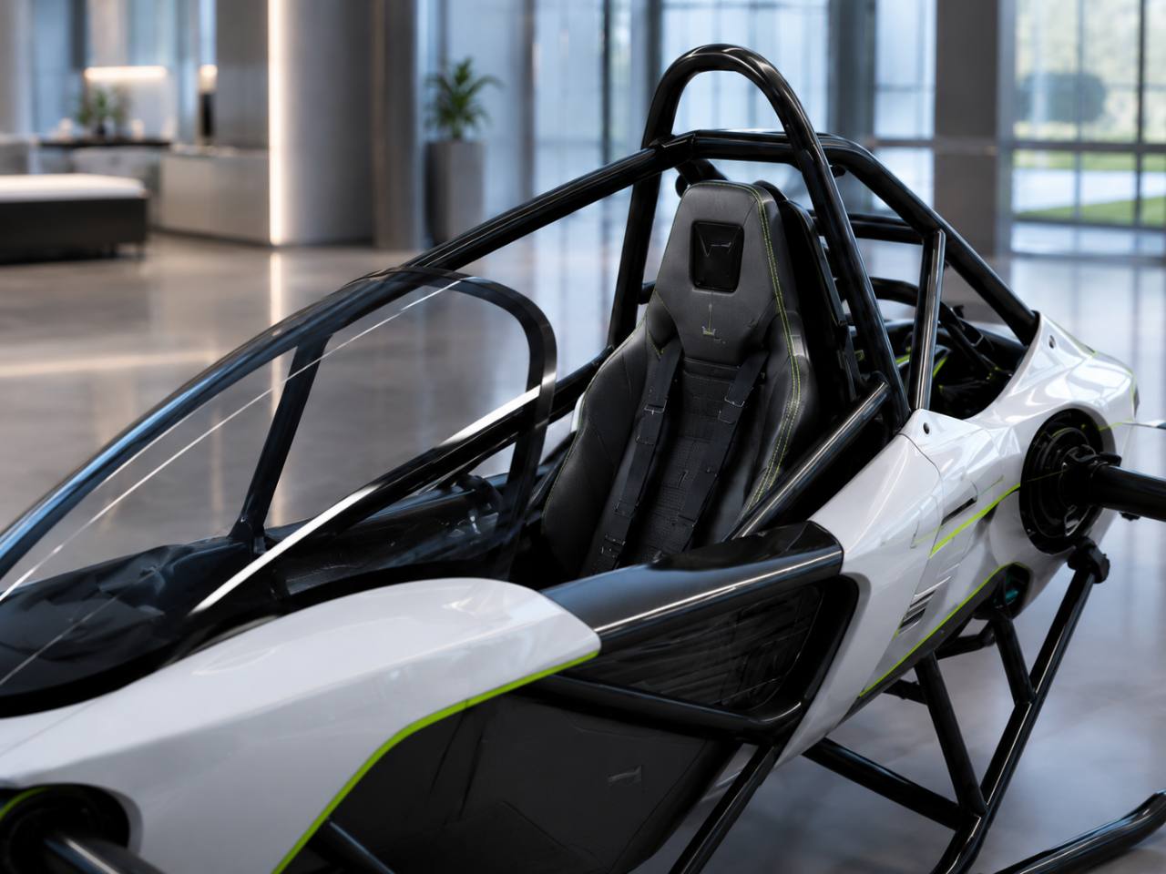
Pilot safety cell
A triangulated tubular frame, multi-point restraint, canopy coverage, landing structure, and defined clearance from rotating components form the occupant protection strategy.
04
Assisted flight modes
Configuration targets include stabilized manual control, hands-free hover, route guidance, envelope limits, landing assistance, and pilot-commanded mode changes.
05
Landing and obstacle sensing
Optional radar or lidar inputs can support height awareness, landing-zone checks, obstacle alerts, and automatic landing logic after engineering validation.
06
Emergency recovery
Abnormal procedures combine warnings, energy reserve guidance, controlled landing logic, occupant restraint, location reporting, and a ballistic parachute option where suitable.
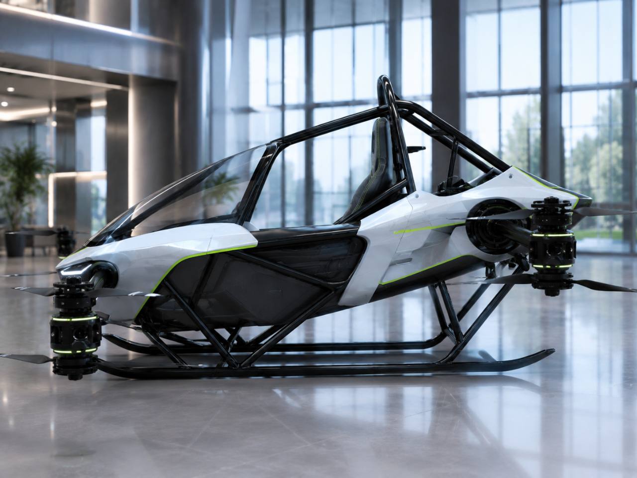
Symmetric four-axis layoutFour lift units sit at the corners of the airframe while energy and control hardware remain close to the protected center structure.
Modular service strategy
Designed around inspection and replacement.
Arm-root controller modules with accessible cooling paths
Protected wiring routes separated from occupant contact areas
Replaceable battery enclosures inside the lower structural envelope
Independent motor monitoring and event logging by channel
Forward sensor cluster with clear ground and approach visibility
Preflight status checks covering energy, controls, sensors, and restraint
These images are original CIITCA concept visualizations. Features shown or described are design objectives and configuration options, not certification evidence or guaranteed production capability. Final systems depend on engineering analysis, testing, mass limits, and applicable regulation.
Aircraft anatomy
One airframe, six visible systems.
This breakdown uses the CIITCA four-axis aircraft itself to show how propulsion, structure, pilot protection, controls, bodywork, and landing hardware fit together.
01
Four-axis propulsion
One brushless electric lift unit sits at each corner, giving the aircraft a clear four-motor, four-arm layout.
02
Lift arms
Lightweight arms carry thrust loads into the central structure while keeping motor wiring and service points accessible.
03
Pilot safety cell
A triangulated tubular frame surrounds the seat and ties the cockpit, arms, and landing structure together.
010203040506
CIITCA four-axis configurationNumbered locations correspond to the system descriptions surrounding the aircraft.
04
Cockpit controls
A pilot-focused control station combines the primary display, single-stick input, system status, and warning cues.
05
Serviceable bodywork
Removable composite panels shape the cockpit while preserving inspection access to structure and installed systems.
06
Landing skids
A wide skid stance supports ground stability, protects the lower structure, and provides replaceable contact points.
Planning targets vary by package, pilot mass, battery choice, operating conditions, reserve policy, and final engineering review. The image is an original CIITCA concept visualization.
Physical layout
Structure and cockpit are part of the system design.
Exterior access, sight lines, restraint geometry, rotor clearance, and component placement are reviewed together rather than as separate styling decisions.
Side profileOpen structural paths and low-mounted landing skids support inspection, transport, and ground handling.Pilot cellCanopy coverage, harness placement, visibility, and frame geometry define the occupant environment.
Safety development
Layers instead of a single feature.
Prevent
Preflight status checks, operating limits, configuration control, battery monitoring, and pilot training.
Detect
Sensor cross-checks, propulsion-channel monitoring, warning prioritization, and event logging.
Respond
Stabilized modes, controlled landing logic, energy reserve guidance, and documented abnormal procedures.
Recover
Landing structure, occupant restraint, emergency-location and parachute options subject to configuration review.
Features described here are design objectives or configuration options. Availability and demonstrated capability must be documented in the final build specification.
Industry-informed design
What current personal eVTOL programs show.
CIITCA uses public industry information to frame buyer questions and engineering priorities. The following are external examples, not CIITCA specifications.
Pivotal Helix
Published specifications include a 20-minute maximum endurance, 55-knot cruise speed, 20-mile range, triple-redundant flight controls, radar-guided autoland, and a ballistic parachute.
Jetson publishes an eight-motor architecture, approximately 20-minute flight time, 102 km/h software-limited speed, redundant batteries, hands-free hover, autoland, and a ballistic parachute.